Configuration Tutorial
This tutorial walks you through the configuration and activation of a USP deployment after installation. It focuses on a typical production scenario where USP forwards external SFTP connections from a business partner to a UDMG Server.
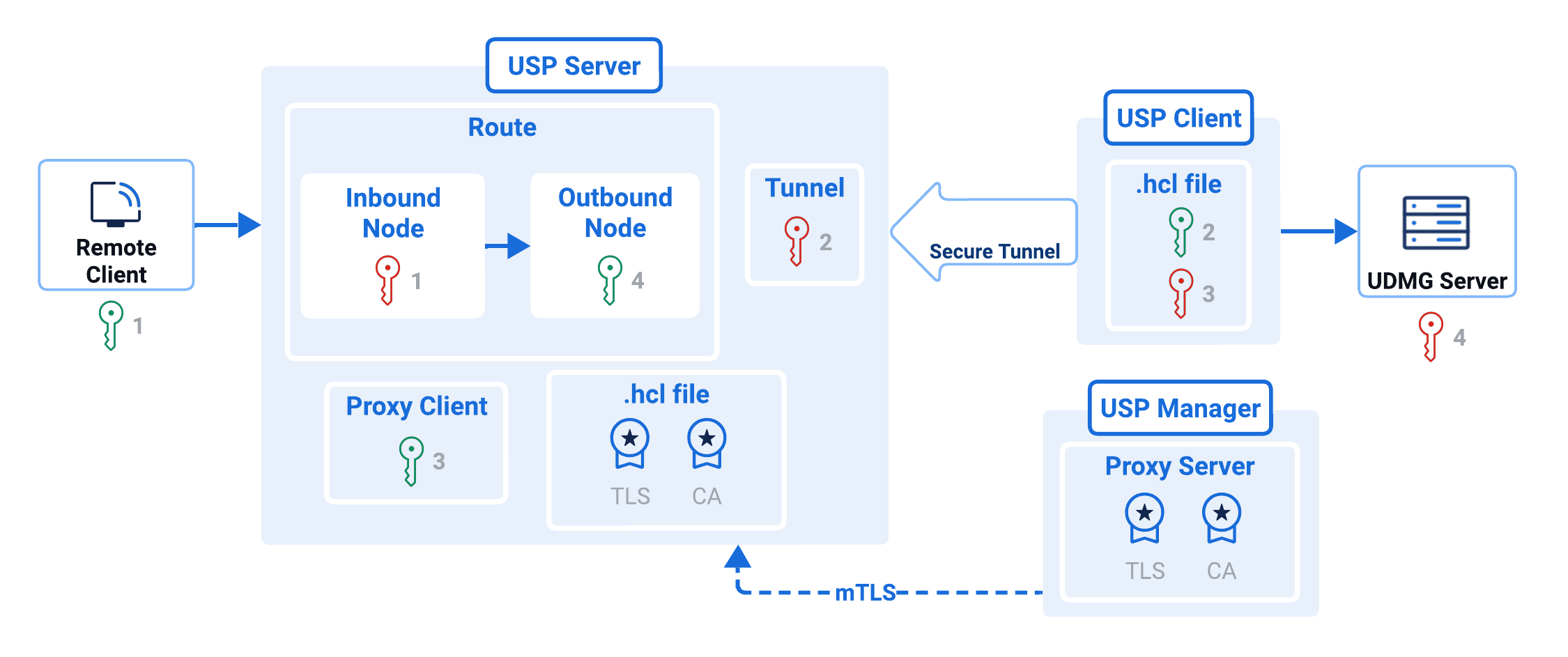
The setup follows Deployment Model 2 - No Pre-Authentication with Credential Passthrough. In this model, USP terminates the inbound SFTP session at the DMZ and relays the client's credentials directly to UDMG for authentication.
In practice, this means:
- An external SFTP client connects to USP.
- USP breaks the session at the DMZ without validating the username or password.
- The client's credentials are forwarded through the Tunnel.
- UDMG performs the actual SFTP authentication and either accepts or rejects the connection.
This guide shows how to define the required keys, certificates, Configuration Items, and deployment logic in the USP Admin UI to enable secure SFTP forwarding.
Prerequisites
Before beginning this tutorial, ensure the following:
USP Manager Installation is complete, including access to the USP Admin UI.
USP Server Installation is complete, including certificates required for USP Manager and USP Server mTLS authentication.
USP Client Installation is complete, including the two sets of public and private key pairs, used for authentication between the USP Client and the USP Server.
You have a private host key (in PEM format) for the Inbound Node, used to authenticate the USP Server to external SFTP clients.
You have the public key content (in OpenSSH host key format) for the Outbound Node, used to verify the identity of the UDMG Server.
Overview
In this tutorial, you will perform the following steps in USP Admin UI to configure a working deployment that forwards SFTP connections to UDMG:
| Step | Description |
|---|---|
| Step 1: Add Two Private Keys | Required to authenticate the USP Server to the SFTP incoming connection and the USP Client. |
| Step 2: Add Two Public Keys | Used to verify the USP Client and the UDMG Server. |
| Step 3: Add a CA Certificate | Certificate authority used to validate the USP Server's TLS certificate. |
| Step 4: Add a TLS Certificate | Certificate and private key that identify the USP Manager to the USP Server. |
| Step 5: Add a Rule | Defines how inbound connections are authenticated and how outbound credentials are sourced. |
| Step 6: Add a Route | Container that links Inbound and Outbound Nodes. |
| Step 7: Add an IP Filter | Controls which inbound IP addresses are allowed (allow all for this tutorial). |
| Step 8: Add an Inbound Node | Virtual server in the DMZ that accepts external connections. The Inbound Node needs its own host key to present to clients. |
| Step 9: Add an Outbound Node | Internal target system that USP forwards traffic to — in this tutorial, the UDMG Server. |
| Step 10: Add a Listener | Port on the USP Server that accepts external incoming connections and maps them to the Route. |
| Step 11: Add a Proxy Server | Represents the USP Server instance in USP Manager, including its TLS settings. |
| Step 12: Add a Tunnel | Port on the USP Server dedicated to accepting connections from given Proxy Clients. |
| Step 13: Add a Proxy Client | Represents the USP Client instance and its public key. |
| Step 14: Add a Deployment | Links the Listener, Proxy Server, Tunnel, and Proxy Client to form an operational deployment. |
| Step 15: Push the Configuration | Push the configuration from USP Manager to the USP Server to activate it. |
At the end of these steps, your USP deployment will be able to accept SFTP connections from an external partner and securely forward them to UDMG.
Steps
Authentication
- For more context on these keys' usage, refer to Keys.
- For more context on these certificates' usage, refer to USP Manager and USP Server mTLS Authentication.
Step 1: Add Two Private Keys
This configuration tutorial demands two Private Keys:
| # | Added to | Purpose | Related Documentation |
|---|---|---|---|
| 1 | Inbound Node | Presented to external incoming connections for host verification. | USP Server Host Key Verification |
| 2 | Tunnel | Used by the USP Server to authenticate itself when accepting connections from the USP Client. | Authentication Between USP Clients and Tunnels |
To add the first Private Key, follow these steps:
- From the Sidebar, click Authentication > Keys.
- Click Private Keys.
- Click Add Private Key.
- Complete the fields following this table:
| Field | Value |
|---|---|
| Name | My_Inbound_Node_Host_Private_Key |
| Description | Private Key used by the USP Server to identify itself to external incoming connections. |
| Key |
info The corresponding public key must already be distributed to and trusted by the SFTP clients. |
- Click Save.
- Repeat steps 1 to 5 using this other table:
| Field | Value |
|---|---|
| Name | My_Tunnel_Private_Key |
| Description | Private Key used by the USP Server to identify itself during incoming connections from USP Clients. |
| Key |
info Its counterpart is the public key found under the If you followed the Generating SSH Keys for USP Tunnels guide, the |
Step 2: Add Two Public Keys
This configuration tutorial demands two Public Keys:
| # | Added to | Purpose | Related Documentation |
|---|---|---|---|
| 1 | Proxy Client | Used by the USP Server to verify the identity of the connecting USP Client during SSH authentication. | Authentication Between USP Clients and Tunnels |
| 2 | Outbound Node | Used to verify the identity of the UDMG Server during SSH handshake. | Remote Host Key Verification in Outbound Nodes |
To add the first Public Key, follow these steps:
- From the Sidebar, click Authentication > Keys.
- Click Public Keys.
- Click Add Public Key.
- Complete the fields following this table:
| Field | Value |
|---|---|
| Name | My_Proxy_Client_Public_Key |
| Description | Public Key used by the USP Server to verify the USP Client identity. |
| Key |
info Its counterpart is the private key found under the If you followed the Generating SSH Keys for USP Tunnels guide, the |
- Click Save.
- Repeat steps 1 to 5 using this other table:
| Field | Value |
|---|---|
| Name | My_Outbound_Node_Remote_Host_Key |
| Description | SSH host key used to verify the identity of the UDMG Server. |
| Key |
info The value can be retrieved from UDMG Admin UI, under the Key Definition section of the Credentials Private Key record. |
Step 3: Add a CA Certificate
This CA Certificate is added to the Proxy Server item and used by the USP Manager to validate the TLS certificate presented by the USP Server during mutual TLS authentication.
To add this CA Certificate, follow these steps:
- From the Sidebar, click Authentication > Certificates.
- Click CA Certificates.
- Click Add CA Certificate.
- Complete the fields following this table:
| Field | Value |
|---|---|
| Name | My_Proxy_Server_CA |
| Description | CA Certificate used by the USP Manager to validate the TLS certificate presented by the USP Server. |
| Certificate |
info If you followed the mTLS Certificates Generation Guide, the |
- Click Save.
Step 4: Add a TLS Certificate
This TLS Certificate is added to the Proxy Server item and used by the USP Manager to identify itself to the USP Server during mutual TLS authentication.
To add this TLS Certificate, follow these steps:
- From the Sidebar, click Authentication > Certificates.
- Click TLS Certificates.
- Click Add TLS Certificate.
- Complete the fields following this table:
| Field | Value |
|---|---|
| Name | My_Proxy_Server_TLS |
| Description | TLS Certificate used by the USP Manager to identify itself to the USP Server. |
| Certificate |
info If you followed the mTLS Certificates Generation Guide, the |
| Key |
info If you followed the mTLS Certificates Generation Guide, the |
- Click Save.
Configuration Items
Once the required certificates and keys have been added, you can begin defining the Configuration Items in USP Manager.
Step 5: Add a Rule
A Rule defines how inbound connections are authenticated and how outbound credentials are sourced. It is central to determine the security posture of the associated Route.
To add a new Rule:
- From the Sidebar, click Configuration > Rules.
- Click Add Rule.
- Complete the fields following this table:
| Field | Value |
|---|---|
| Name | My_Rule |
| Description | A Rule with no pre-authentication and credential passthrough. |
| Inbound Authentication Method | Password |
| Authentication at the Proxy | Disabled |
| Outbound Credential Source | Passthrough Credentials |
| ICAP Scanner | None |
- Click Save.
This Rule configuration means credentials are not validated at the proxy; however, a username and password are expected before the session break, which are then passed to the UDMG Server for authentication.
Step 6: Add a Route
A Route is a container for Inbound Nodes and Outbound Nodes.
To add a Route, follow these steps:
- From the Sidebar, click Configuration > Routes.
- Click Add Route.
- Complete the fields following this table:
| Field | Value |
|---|---|
| Name | My_Route |
| Description | A Route from the the Inbound Node to the UDMG Server Outbound Node. |
- Click Save.
Step 7: Add an IP Filter
An IP Filter defines which source IP addresses are allowed or blocked when connecting to USP Server. For this tutorial, you will create an IP Filter that allows all incoming connections. This filter will be assigned to the Inbound Node in the next step.
To add an IP Filter:
- From the Sidebar, click Authentication > IP Filtering.
- Click Add IP Filter.
- Complete the fields following this table:
| Field | Value |
|---|---|
| Name | My_IP_Filter |
| Description | An IP Filter that allows all incoming connections. |
| Default Action | Allow. |
Step 8: Add an Inbound Node
An Inbound Node defines the virtual server configuration on a USP Server instance that handles incoming client connections.
To add an Inbound Node, follow these steps:
- Within the Route's page, go to the Inbound Nodes tab.
- Click Add Inbound Node.
- Complete the fields following this table:
| Field | Value |
|---|---|
| Name | My_Inbound_Node |
| Description | Inbound Node that defines the virtual server configuration. |
| IP Address Filter List | My_IP_Filter |
| Priority Number | 1 |
| Rule | My_Rule |
| Host Private Key | My_Inbound_Node_Host_Private_Key |
Step 9: Add an Outbound Node
This Outbound Node defines the configuration for the UDMG Server to which the USP Server connects.
To add an Outbound Node, follow these steps:
- Back on the Route's page, go to the Outbound Nodes tab.
- Click Add Outbound Node.
- Complete the fields following this table:
| Field | Value |
|---|---|
| Name | My_Outbound_Node |
| Description | Outbound Node that defines the configuration for the UDMG Server. |
| Hostname | IP address or domain name of the UDMG Server. |
| Port | Port of the UDMG Server. |
| Remote Host Key | My_Outbound_Node_Remote_Host_Key |
- Click Save.
Step 10: Add a Listener
A Listener defines the port on which a USP Server accepts external incoming connections and specifies the Outbound Node that connects to the UDMG Server.
To add a Listener, follow these steps:
- From the Sidebar, click Configuration > Listeners.
- Click Add Listeners.
- Complete the fields following this table:
| Field | Value |
|---|---|
| Name | My_Listener |
| Description | Listener that defines the port on which the USP Server instance accepts SFTP incoming connections. |
| Port | USP Server port for external incoming connections. |
| Route | My_Route |
| Default Outbound Node | My_Outbound_Node |
- Click Save.
Step 11: Add a Proxy Server
A Proxy Server is the top-level Configuration Item that represents a specific USP Server instance.
To add a Proxy Server, follow these steps:
- From the Sidebar, click Configuration > Proxy Servers.
- Click Add Proxy Server.
- Complete the fields following this table:
| Field | Value |
|---|---|
| Name | This name must match exactly the name configured in the name field of the USP Server's .hcl configuration file. |
| Description | Proxy Server representing my USP Server instance. |
| Hostname | USP Server instance's IP address or domain name. |
| Port | This port must match exactly the port configured in the web.config_host field of the USP Server's .hcl configuration file (default value is 8900). |
| CA Certificate | My_Proxy_Server_CA |
| TLS Certificate | My_Proxy_Server_TLS |
The Common Name (CN) or Subject Alternative Name (SAN) fields in the TLS Certificate must match. If there's a mismatch, mTLS authentication between the USP Manager and USP Server fails.
- Click Save.
Step 12: Add a Tunnel
A Tunnel defines a port within a Proxy Server, which is dedicated to accepting connections from a list of Proxy Clients.
To add a Tunnel, follow these steps:
- Within the Proxy Server's page, go to the Tunnels tab.
- Click the Add Tunnel button.
- Complete the fields following this table:
| Field | Value |
|---|---|
| Name | My_Tunnel |
| Description | Tunnel that defines the port dedicated to accepting connections from Proxy Clients. |
| Port | This port must match exactly the port configured in the tunnel.port field of the USP Client's .hcl configuration file (default value is 8900). |
| Private Key | My_Tunnel_Private_Key |
- Click Save.
Step 13: Add a Proxy Client
A Proxy Client represents an instance of a USP Client.
To add a Proxy Client:
- From the Sidebar, click Configuration > Proxy Servers.
- Click the Name of the Proxy Server you created earlier.
- Go to the Tunnels tab.
- Click My_Tunnel.
- Go to the Proxy Clients tab.
- Click the Add Proxy Client button.
- Complete the fields following this table:
| Field | Value |
|---|---|
| Name | This name must match exactly the name configured in the name field of the USP Client's .hcl configuration file. |
| Description | Proxy Client that represents my USP Client instance. |
| Public Key | My_Proxy_Client_Public_Key |
Step 14: Add a Deployment
Deployments tie a Listener to a specific USP Server and optionally associate it with a tunnel and client configuration. This is the final step before activating your configuration.
To add a Deployment:
- From the Sidebar, click Configuration > Listeners.
- Click the Listener named My_Listener.
- Go to the Deployments tab.
- Click Add Deployment.
- Complete the fields following this table:
| Field | Value |
|---|---|
| Proxy Server | Select the name of the Proxy Server added earlier. |
| Startup Mode | Auto |
| Description | Deployment linking the Listener to the specified USP Server, Tunnel, and Proxy Client. |
| Tunnel | My_Tunnel |
| Proxy Client | Select the name of the Proxy Client added earlier. |
- Click Save.
Push Configuration
Step 15: Push the configuration
Now, everything is set up to push the configuration to the USP Server. To do so:
- From the Sidebar, click Monitoring > Status.
- The Proxy Server that was added before appears in the list
- Click the Name of the USP Server instance.
- The Proxy Server Details are displayed. The Server Status should display Online
- Go to the Configuration tab.
- A side-by-side comparison of the current configuration on the USP Server instance versus the new configuration is displayed.
- Click Push Configuration.
- A success message should appear at the bottom right of the screen.
- Go to the Details tab.
- The status of the USP Server's Tunnels and Listeners are reported on the bottom of the page.
- Go to the Live Tunnels tab.
- The Tunnel is listed as running and the Proxy Client is reported in the Connected Client column.
Deployment Complete
At this point, your USP Server is fully configured and ready to operate:
- The USP Server listens for inbound SFTP connections on the configured Listener's port.
- Upon receiving a connection, the session break mechanism terminates the client session, authenticates it as configured, and initiates a second connection to the internal UDMG server over a secure SSH tunnel.
- Once the USP Server authenticates the forwarded connection, data and commands flow between the external client and internal target, with the USP Server acting as a secure, controlled intermediary.
For more information on configuration options, tunneling strategies, and advanced deployment models, refer to the corresponding documentation sections.