Configuration
UDMG Secure Proxy (USP) provides a flexible and centralized configuration system that governs the behavior of all USP components. This system defines:
- Proxy routing logic: How inbound connections are forwarded to internal targets.
- Authentication behavior: How credentials are validated and propagated across the connection path.
- Secure communication setup: How USP establishes trusted control and data channels using tunnels, keys, and certificates.
Configuration Items Overview
At the core of this system are Configuration Items, which are modular entities that encapsulate individual aspects of the proxy behavior. Some of these Configuration Items are reusable, while others are not. All of them are created and managed within USP Manager, then pushed to USP Server instances to activate secure, predictable runtime behavior.
Configuration Items are the building blocks that define the behavior of USP Server and Client instances. Many items are reusable across deployments, helping streamline configuration and minimize the risk of errors.
| Name | Description |
|---|---|
| Proxy Server | The top-level Configuration Item that represents a specific USP Server instance. |
| Deployment | Defines which Listener is launched on a specific USP Server instance and connects the USP Server with a Tunnel and a Proxy Client. |
| Listener | Defines the port on which a USP Server accepts inbound connections and specifies the Outbound Node that connects to the internal target. |
| Route | Groups a set of Inbound Nodes and Outbound Nodes. |
| Inbound Node | Defines the virtual server configuration on a USP Server instance that handles incoming client connections. |
| Rule | Defines how a USP Server instance authenticates incoming connections and manages credentials during the proxying process. |
| Outbound Node | Defines the configuration for the internal target to which the USP Server connects. |
| Tunnel | Defines a port within a Proxy Server, which is dedicated to accepting connections from Proxy Clients. |
| Proxy Client | Represents a USP Client instance that connects to a USP Server through a specific Tunnel. |
Two additional Configuration Items can be used to authenticate external incoming connections:
| Name | Description |
|---|---|
| Account Repository | A container that stores Accounts. |
| Account | A set of credentials stored within an Account Repository. |
Configuration Items Lifecycle
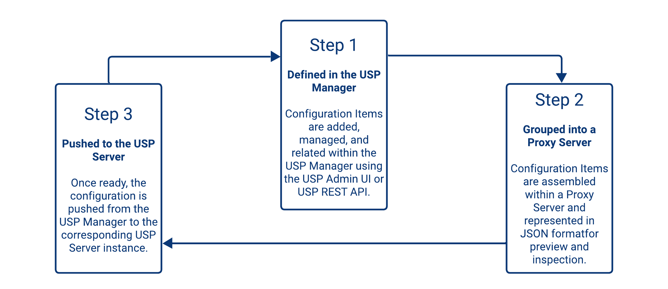
The USP architecture is designed to separate configuration design (in USP Manager) from runtime execution (in USP Server), ensuring secure, consistent, and versioned deployments.
Configuration Items Relationship
Structural Relationships
Configuration Items in USP relate to each other in two structural ways: by reference or containment. Understanding these relationships is essential for modeling scalable, modular, and maintainable configurations.
- Reference-based relationships occur when a Configuration Item includes a field that points to another item by its unique identifier. These are always one-to-one: an item can reference only one instance of another.
- Example: A Deployment references a Proxy Server via its Proxy Server field.
- Containment-based relationships occur when a Configuration Item includes one or more child items directly within its structure. These relationships are typically one-to-many: a parent may contain multiple instances of another item.
- Example: A Route contains multiple Inbound Nodes and Outbound Nodes. These nodes do not exist independently and are defined as part of the Route's structure.
This structural design enables:
- Reuse of Configuration Items through references, allowing shared components like Rules or Routes.
- Encapsulation of logic within parent items for components that naturally belong together, such as Nodes within a Route.
The table below summarizes all structural relationships between Configuration Items.
The table should be read in a row → column order. For example:
- The first row reads "Proxy Server → Tunnel = Contains one or many", meaning Tunnels are added within the scope of a single Proxy Server.
- The second row reads "Deployment → Proxy Server = References one", meaning that when adding a Deployment, it must reference a Proxy Server.
| Proxy Server | Deployment | Listener | Tunnel | Proxy Client | Route | Inbound Node | Outbound Node | Rule | Account Repository | Account | |
|---|---|---|---|---|---|---|---|---|---|---|---|
| Proxy Server | - | - | - | Contains one or many | - | - | - | - | - | - | - |
| Deployment | References one | - | - | References one (or two) (*) | References one (or two) (*) | - | - | - | - | - | - |
| Listener | - | Contains one or many | - | - | - | References one | - | References one | - | - | - |
| Tunnel | - | - | - | - | Contains one or many | - | - | - | - | - | - |
| Proxy Client | - | - | - | - | - | - | - | - | - | - | - |
| Route | - | - | - | - | - | - | Contains one or many | Contains one or many | - | - | - |
| Inbound Node | - | - | - | - | - | - | - | - | References one | - | - |
| Outbound Node | - | - | - | - | - | - | - | - | - | - | - |
| Rule | - | - | - | - | - | - | - | - | - | References one | - |
| Account Repository | - | - | - | - | - | - | - | - | - | - | Contains one or many |
| Account | - | - | - | - | - | - | - | - | - | - | - |
The relationships outlined above can also be visualized in the following relational diagram:
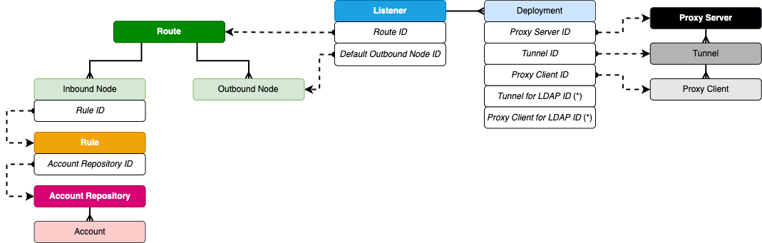
(*) Deployments are a special case: they can reference one Tunnel and one Proxy Client for connections to internal targets, and optionally the same Tunnel and Proxy Client (or different) for connecting to LDAP servers. But they are still set in two different pairs of fields.
Logical Relationships
While Structural Relationships describe how Configuration Items are assembled to support modular reuse and scalable design, logical relationships illustrate how those items work together at runtime to define the behavior of a USP Server instance.
All Configuration Items are defined and managed in USP Manager and are grouped under a Proxy Server, which acts as the root container for a complete configuration. When a configuration is pushed, all associated items are deployed to a specific USP Server instance.
The diagram below illustrates the logical relationships between Configuration Items:
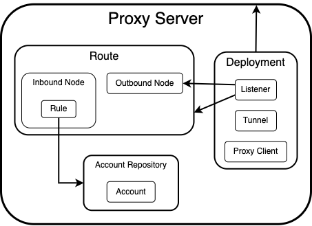
- At the top of the hierarchy is a Proxy Server, a logical container for all related Configuration Items that points to a specific USP Server instance.
- A Deployment links a Proxy Server to a Tunnel and a Proxy Client. It also defines which Listener should be activated.
- The Listener references a Route to determine how to process each connection, and selects one of the Route's Outbound Nodes as the destination for forwarding the authenticated external incoming connection.
- The Route groups together one or more Inbound Nodes and Outbound Nodes.
- Each Inbound Node specifies how inbound connections are matched (e.g., by IP range), authenticated (via a Rule), and secured (using a host private key).
- The Rule applied to an Inbound Node defines how inbound credentials are validated and whether they should be reused for outbound connections.
- A rule may reference an Account Repository for validating external incoming connections.
- Each Account Repository contains one or more Accounts (a set of credentials).
- Outbound Nodes define where the connection is forwarded, usually to an internal target behind a firewall.
In addition to linking to one another, some Configuration Items reference Authentication Items (such as Private Keys, Public Keys, and CA Certificates) to enable secure communication. For more details, refer to Authentication.