OpenShift Start-Up Guide
Introduction
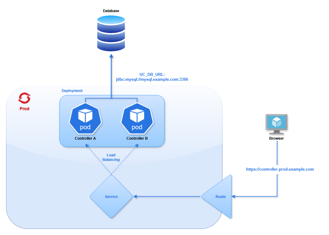
This guide provides an example setup to get started with Red Hat OpenShift 4.17 for Universal Automation Center. It describes how to configure a single project with the following:
- 2 Universal Controller pods in High Availability
- 1 Universal Agent pod running OMS
- 2 Universal Agent pods running UAG
- 1 non-OpenShift Universal Agent running UAG
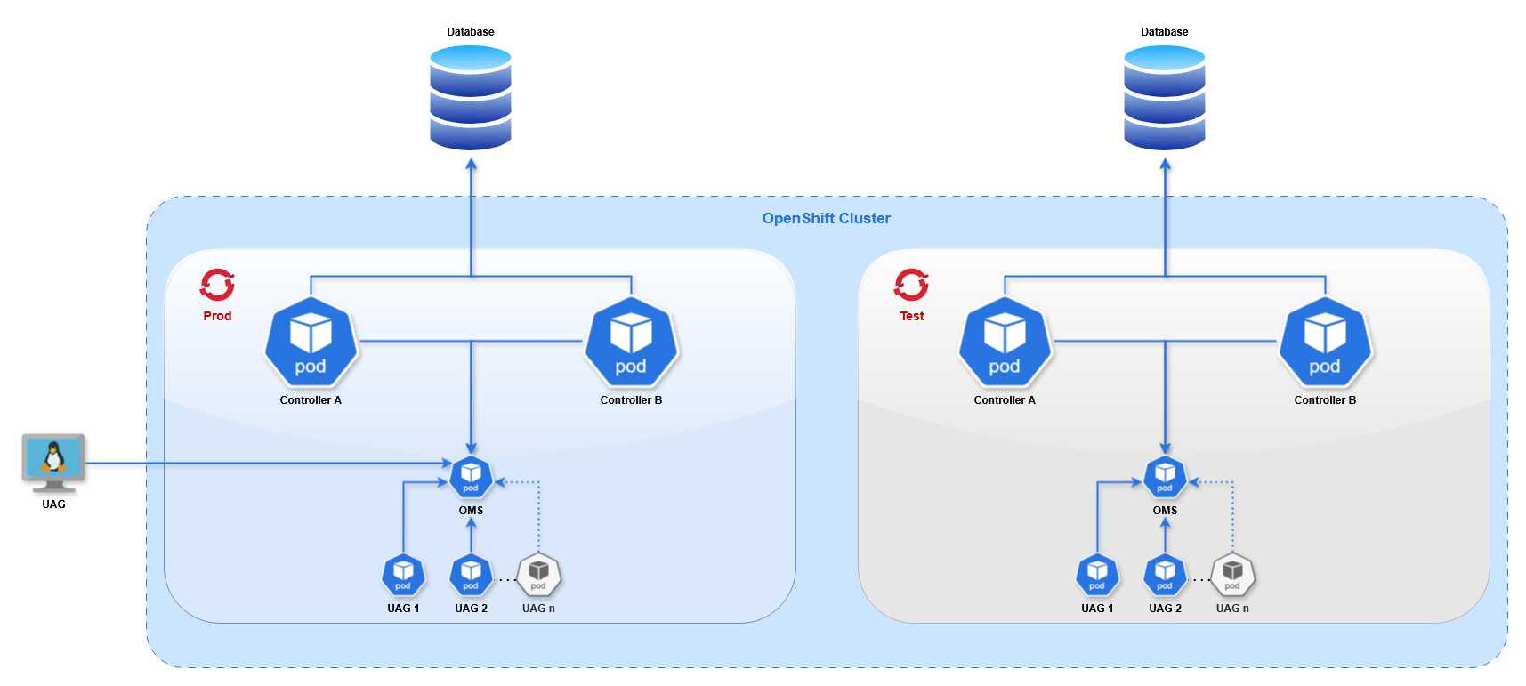
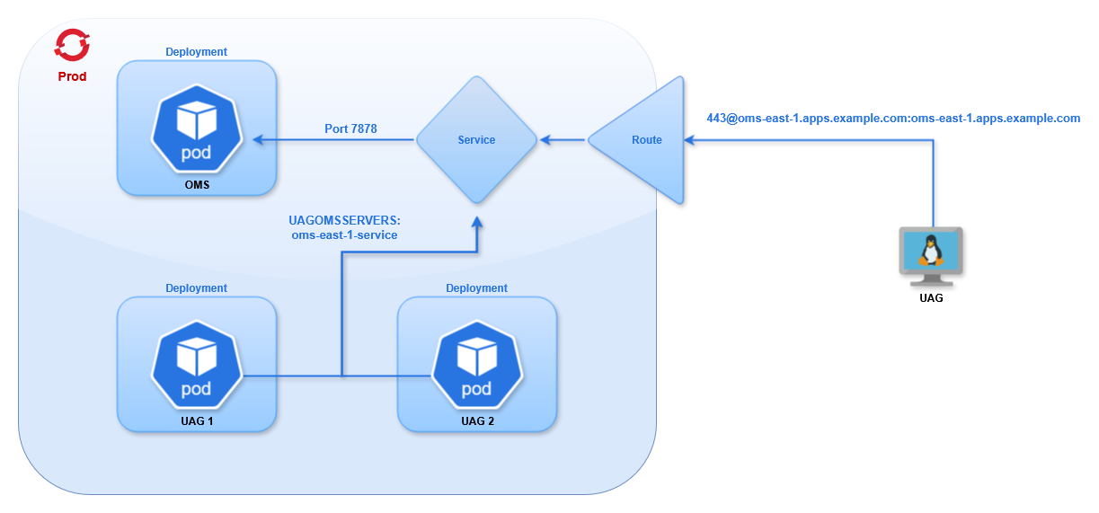
This diagram shows 2 OpenShift projects, "Prod" and "Test", to demonstrate that multiple projects can operate in the same cluster. Throughout this document we only use the "Prod" project.
Terminology
Throughout this document we use a set of terms specific to OpenShift. Other container platforms (such as Kubernetes) may use different terms for the same resources. This table provides a brief overview of each term (additional information can be found in OpenShift's Documentation).
Term | Definition |
|---|---|
Cluster | A Cluster refers to all resources or activities in the OpenShift environment, distinct from any other activities running on separate hardware or a separate cloud environment. |
Node | A physical (or virtual) machine that runs the OpenShift cluster. In a standard configuration, the cluster runs across 5 nodes. The pods run in a containerized layer across the nodes. |
Deployment | A Deployment handles the process of rolling out updates to applications and ensuring the correct number of pods are running. |
Pod | A pod typically comprises one application, running on one or more container(s). It is the smallest compute unit. The Universal Controller runs in a pod, and the Universal Agent runs in a different pod. |
Image | The blueprint for a pod, containing all of the packages needed for the application. |
Service | A service allows traffic to be load balanced into a set of pods. A service provides an IP address for a pod (or set of pods) inside the cluster. Other pods in the cluster can communicate via a service. |
Route | A route exposes a service outside the cluster. This allows external clients to connect to pods inside the cluster, such as the UI for the Universal Controller or the OMS port for the Universal Agent. |
Cluster Configuration
Installing the OpenShift cluster is beyond the scope of this document. The process varies depending on the platform and resource requirements, so follow the OpenShift Installation documentation for your use case.
The HAProxy load balancer timeout configuration needs to be updated to be compatible with the Heartbeat Interval of the Universal Agents. The timeouts must be longer than the Agent Heartbeat interval, otherwise the agents will continually disconnect and reconnect to OMS as the proxy timeout elapses.
In HAProxy's configuration file (located at /etc/haproxy/haproxy.cfg) set the value in the ingress-router section:
listen ingress-router-443
  bind *:443
  mode tcp
  balance source
  timeout server 150s
  timeout client 150s
In this example we use 150 seconds, as the default Heartbeat Interval is 120 seconds. If you change the heartbeat of any agent in the cluster to a longer duration the proxy configuration must be updated accordingly.
Other load balancers will need a similar configuration. Once an external UAG is connected to an OMS pod, the configuration can be verified by waiting a few minutes to ensure they do not disconnect.
Creating Resources
Throughout this document we define resources as YAML. There are two ways to create resources in OpenShift:
- oc cli
- UI Import
Once logged in (see OpenShift CLI), you can run oc create -f FILENAME.yml to create resources. The format of the YAML file is the same as the Import YAML screen.
In the top-right corner of the UI clicking the Plus button will take you to a page where you can paste in YAML for any resource type.

OpenShift CLI
The oc command line utility provided with Red Hat OpenShift allows you to manage cluster operations and applications from a terminal.
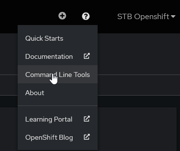
To download oc select Command Line Tools from the Question Mark menu in the UI.
Select the download package for your platform (we will be using Linux x86_64), download it, and extract it.
First, log in to the cluster using the API endpoint. There are two recommended methods for authentication.
- Interactive
- Token
Interactive
Log in without a password, and you will be prompted to enter the password.
# oc login https://api.openshift.example.com:6443 -u stb.openshift
The server uses a certificate signed by an unknown authority.
You can bypass the certificate check, but any data you send to the server could be intercepted by others.
Use insecure connections? (y/n): y

WARNING: Using insecure TLS client config. Setting this option is not supported!

Console URL: https://api.openshift.example.com:6443/console
Authentication required for https://api.openshift.example.com:6443 (openshift)
Username: stb.openshift
Password:
Login successful.

You have access to the following projects and can switch between them with 'oc project <project-name>':

* openshift-image-registry
prod

Using project "openshift-image-registry".
Welcome! See 'oc help' to get started.
Print the authentication token (for use later)
# oc whoami -t
sha256~8XNsLXzHkpbCaxgGcOx5YHnFjNpWr4oetbK8W7yOra1
Token
In the Command Line Tools page select Copy login command.

In the next page click Display Token.

This provides an oc command with a token that you can paste in the terminal to log in.
Once you have logged in you can run commands to view and edit cluster resources.
# oc get deployments
NAME     READY   UP-TO-DATE   AVAILABLE   AGE
agent1   0/1     1            0           2s
Additional information on oc syntax can be found in the OpenShift Documentation.
SSL Certificates
In the Interactive example above we ignore the self-signed TLS certificates provided by the cluster. In production we recommend using certificates issued from a trusted Certificate Authority, and not self-signed certificates.
In the event a self-signed certificate is required use the following steps to add the cluster's certificates to the local trust store on the system where you run oc.
Configure Certificates
Step | Description |
|---|---|
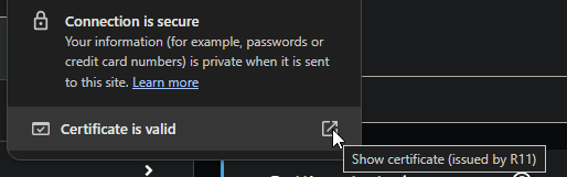
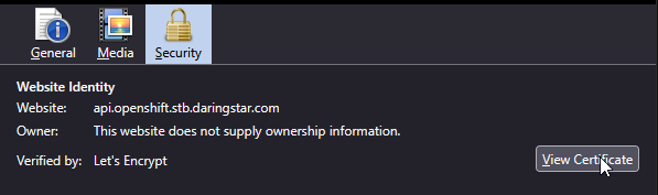
Download the certificates | Downloading the certificates from a web browser should work in all scenarios. (Alternatively, you can request the full chain from the administrator who created them). Navigate to the cluster's web UI and view the certificate in the browser.
ChromeClick the button next to the URL.
Click Show Connection Details.
Click Show Certificate.
In the popup window select each certificate in the Certificate Hierarchy, click Export, and save it. With all of the certificates downloaded, combine them into a single file. Repeat the steps for the API endpoint. FirefoxClick the lock icon next to the URL.
Click Connection Secure.
Click More Information.
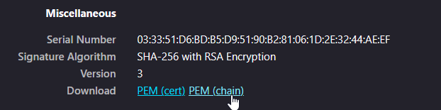
In the popup's Security tab click View Certificate.
In the Miscellaneous section click PEM (chain).
This will download the full chain for the URL. Repeat the process for the API endpoint. Combine the 2 chains together |
Add to local trust store | This process will vary depending on the platform. The following example is for Red Hat systems. Copy the CA certificate to the system's trusted authorities. Update the certificate list to enable the new route. |
Verify the certificate | First, log out of your Next, delete the existing kube configuration file. This includes our preference to ignore the certificates, which we want to remove. Log in again. It should not prompt you to ignore the certificate. |


Pushing Images to the Cluster
In order to deploy Universal Controller or Universal Agent pods you must obtain the corresponding Docker images and add them the cluster's Image Registry.
Universal Controller images are available in the Customer Portal. A customer username and password (provided by Stonebranch, Inc.) are required to access the Customer Portal.
Universal Agent images are also available in the Customer Portal. Alternatively, you can pull an image directly from the Red Hat Image Catalog using the instructions on that page.
We will describe the procedure for uploading an image from the Customer Portal, since it can apply to both Agent and Controller.
Depending on the environment the default route for the Image Registry may not be enabled. This must be enabled to push images to the registry. The following command enables the route.
oc patch configs.imageregistry.operator.openshift.io/cluster --patch '{"spec":{"defaultRoute":true}}' --type=merge
To push the images you must use either Docker or Skopeo (a utility from Red Hat for managing Docker images). Both solutions require an authentication token. Steps for obtaining a token can be found in OpenShift CLI.
The steps below describe the process for a Universal Controller image, but the same steps apply for the Universal Agent images as well. There are two methods for pushing images to the cluster:
- Skopeo (Recommended)
- Docker
Skopeo
Skopeo uses a single command to import, tag, and push the image.
First, you need to get the Image Registry route, which can be obtained with an oc command:
export HOST=$(oc get route default-route -n openshift-image-registry --template='{{ .spec.host }}')
Then you can run Skopeo.
skopeo copy \
  --dest-creds=$(oc whoami):$(oc whoami -t) \
  docker-archive:./universal-controller-7.8.0.0-build.95-docker-rhel-ubi9-x86_64.tar.bz2 \
  docker://$HOST/prod/universal-controller:7.8.0.0
In the command we provide the credentials as a username and token. Here we use oc to get both, but they can be provided as strings.
The source is the local image file, specified as a docker archive.
The destination uses the Image Registry route, the project name, the image name, and the desired remote tag.
Docker
Pushing an image with Docker requires several steps, and the Docker daemon must be running.
Step | Description |
|---|---|
Login | First, connect Docker to the cluster by logging in to the Image Registry route, which can be obtained with an oc command: Then you can login. |
Import | Next, the image must be imported into the local image repository. Navigate to the directory where the image was downloaded and load it. After successfully loading the image you can list it and see its tags. |
Tag | Next, set the remote tag for the image as it will appear in the cluster. The format is: For example: |
Push | Finally, push the image to the cluster, specifying the remote image by name and tag. |
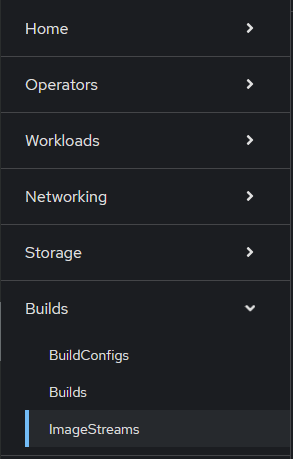
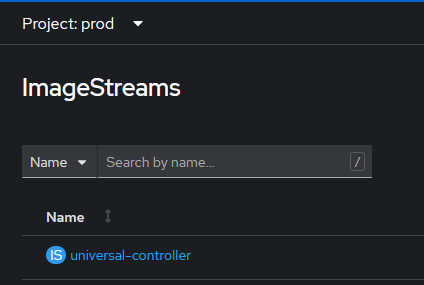
With the image pushed you can verify it exists in the cluster in the ImageStreams page.

Universal Controller Setup
We will deploy two Universal Controllers in a High Availability configuration using a single external MySQL database. The OpenShift controllers will use Deployment API Objects. This will allow you to modify the configuration (such as the Environment Variables), and OpenShift will rollout new pods with the latest configuration. This is not possible with a standalone pod. Changing the configuration is not allowed, so you would have to delete the existing pod and define a new one.
Database
In this guide we use a MySQL database that resides in a Virtual Machine outside of the OpenShift cluster. The database configuration is beyond the scope of this document. For more information see Installing a Database.
We use mysql.example.com for the hostname of our example database.
Database Secret
The database credentials must be provided in the Controller Deployment. The password should not be stored in plaintext, so you must create a Secret that the Deployment can reference. The following YAML creates the secret.
apiVersion: v1
kind: Secret
metadata:
  name: mysql-secret
  namespace: prod
stringData:
  password: super-secret-p4ssw0rd
Once created you can access the password field of the Secret in other resources.
Controller
For the Universal Controllers we will create a Deployment with two pods, a Service to load balance between the pods, a Route for exposing the Service outside of the cluster, and a Secret for providing certificates to the pods.
Throughout this section any certificates are truncated and invalid. Valid certificates must be supplied for the connections to work correctly.
Controller Secret
The Route uses Re-encrypt TLS termination, which is described in detail in the Controller Route section. This route type requires a certificate and private key to be configured for Tomcat, as described in the Controller Image documentation. These are provided via a Secret.
apiVersion: v1
kind: Secret
metadata:
  name: uc-east-1-certs
  namespace: prod
stringData:
  cert: |-
    -----BEGIN CERTIFICATE-----
    MIIGATCCA+mgAwIBAgIUYNs+Ai82V9hBYfAZzNICwNCdPNQwDQYJKoZIhvcNAQEL
    n7f0n38=
    -----END CERTIFICATE-----
  key: |-
    -----BEGIN PRIVATE KEY-----
    MIIJQgIBADANBgkqhkiG9w0BAQEFAASCCSwwggkoAgEAAoICAQC9sUl1XfQoHz9+
    AFhYBLQV3D5wsZ1BV5PQlaOj6aT7+g==
    -----END PRIVATE KEY-----
  password: super-secret-p4ssw0rd
Here we define three fields: one for the Certificate, one for the Private Key, and one for the password of the keystore generated by the entry-point script. The name of each field is arbitrary, but they will be used in the Deployment definition.
Controller Deployment
The following YAML creates a Deployment containing two Universal Controllers.
- Deployment
- Description
apiVersion: apps/v1
kind: Deployment
metadata:
  name: uc-east-1
  namespace: prod
spec:
  replicas: 2
  strategy:
    type: RollingUpdate
    rollingUpdate:
      maxSurge: 1
      maxUnavailable: 1
  selector:
    matchLabels:
      app: uc-east-1
  template:
    metadata:
      labels:
        app: uc-east-1
    spec:
      enableServiceLinks: false
      volumes:
        - name: uc-cert
          secret:
            secretName: uc-east-1-certs
            defaultMode: 420
      containers:
        - name: uc-container
          image: image-registry.openshift-image-registry.svc:5000/prod/universal-controller:7.8.0.0-ubi9
          imagePullPolicy: IfNotPresent
          volumeMounts:
            - name: uc-cert
              mountPath: /certs
          resources:
            limits:
              cpu: "4"
              memory: 8Gi
            requests:
              cpu: 500m
              memory: 2000Mi
          env:
            - name: UC_DB_RDBMS
              value: mysql
            - name: UC_DB_URL
              value: jdbc:mysql://mysql.example.com:3306/
            - name: UC_DB_USER
              value: root
            - name: UC_DB_NAME
              value: UCEAST1
            - name: UC_DB_PASSWORD
              valueFrom:
                secretKeyRef:
                  name: mysql-secret
                  key: password
            - name: UC_SYSTEM__IDENTIFIER
              value: Prod Controller 1
            - name: UC_LICENSE
              value: <license key>
            - name: UC_NODE_TRANSIENT
              value: 'true'
            - name: CATALINA_OPTS
              value: '-XX:MaxRAMFraction=2'
            - name: TOMCAT_CERT_PATH
              value: /certs/cert
            - name: TOMCAT_KEY_PATH
              value: /certs/key
            - name: KEYSTORE_PASSWORD_FILE
              value: /certs/password
Configuration | Description |
|---|---|
| The name of the Deployment is |
| We use two pods (one active and one passive), which is determined by the |
| The Deployment Strategy defines how new pods replace old pods, such as during a configuration change. The With these values a rollout will create 1 pod and stop 1 pod at roughly the same time. When the new pod is running and the old pod is terminating, it will move on the next batch and repeat the process. These values must be set according to each use case. This is particularly important when the number of replicas is larger than 2. If there are 10 replicas, and maxSurge is set to 3, during a rollout there can be up to 13 pods in the Deployment. The configuration must account for the resources of the Nodes, and whether they can handle the load of the additional pods during the rollout. Additional information on Deployment Strategies can be found in the OpenShift Documentation. warning This configuration will determine the availability of the Controllers during a configuration change. When pods are stopped and new pods are started there can be downtime caused by the Controllers failing over to the new pods. The duration of this downtime is minimal, roughly the duration for Tomcat to start and bootstrap. |
| The selector tells the Deployment which Pods to manage based on a label, which is why the |
| We apply the label |
| By default Openshift adds an Environment Variable for each parameter in every Service definition in the entire project into the container. This means that as the number of services increases by 1, the number of environment variables in the container will increase by roughly 8. This can cause issues, as there is a limit to the number of environment variables you can set in Linux. The option |
| The Secret created in the previous step is added as a volume, which gets mounted inside the container. Default file permissions for the Secret's files will be |
| We define a single container, which uses the image |
| The image will only be pulled if it does not exist on the disk. Alternatively, you can set the policy to |
| The volume for the secret gets mounted inside the container in the directory |
| The resource definition can specify a Request and Limit. The |
| The Universal Controller configuration is handled by Environment Variables. These variables begin with |
| The Controller is set to transient, meaning when the instance is stopped it will be removed from the Cluster Nodes (not to be confused with the OpenShift Cluster's nodes). This is necessary for redeployment and scaling, to prevent destroyed instances from remaining in the Cluster Nodes and having to be manually deleted. Additional configuration options can be found in the Universal Controller documentation. info The values for the Environment Variables must be strings, which is why any integer and boolean values must be quoted. |
| These are the options for Tomcat's certificates. The image's entrypoint script handles these three Environment Variables. It takes the certificate ( |
| The |
Memory Configuration
Tomcat's memory configuration will be handled by an environment variable, either CATALINA_OPTS or JAVA_OPTS. Both are used when starting Tomcat, but only JAVA_OPTS is used when stopping Tomcat. For the memory configuration specifically, either variable can be used.
The default behavior for Tomcat is to set the maximum heap size to 25% of the available system memory. In OpenShift the available memory is determined in one of two ways, depending on the Pod's configuration.
If no resource limits are defined for the Pod the available memory will be the total memory of the Node. This can allow the controller to use more memory than expected.
If resource limits are defined Tomcat will interpret the memory limit as the total system memory. This is because the Java option -XX:+UseContainerSupport is set by default, so Java is aware of the resource limit, treating it like the total memory of a Virtual Machine. This means Tomcat will be limited to 25% of the resource limit.
With this in mind there are 2 ways to configure the memory for Tomcat:
- Dynamic (Recommended)
- Static
Dynamically set Max Heap Size
The value for the Max Heap Size can be set dynamically based on the Pod's resources.
apiVersion: apps/v1
kind: Deployment
spec:
template:
spec:
containers:
- name: uc-container
resources:
limits:
memory: 8Gi
requests:
memory: 2000Mi
env:
- name: CATALINA_OPTS
value: '-XX:MaxRAMFraction=2'
Here we set the Pod's memory limit to 8GB, which is enforced by OpenShift.
Then we define the fraction of the memory limit to allocate to Tomcat using the -XX:MaxRAMFraction value, which defaults to 4.
This will give us a Max Heap Size of 4096MB, derived from memory limit (8GB) divided by MaxRAMFraction (2).
Statically set Max Heap Size
We can set a static value for the Max Heap Size using the Xmx option.
apiVersion: apps/v1
kind: Deployment
spec:
template:
spec:
containers:
- name: uc-container
env:
- name: CATALINA_OPTS
value: '-Xmx4096m'
Using -Xmx means the resource limit is not relevant for the Tomcat configuration.
This will use 4096MB as the Max Heap Size, regardless of the Node or Pod resources.
The dynamic option is preferred. It allows the heap size to scale with the memory limit. We also recommend defining resources on the Pods, so it makes sense to utilize those values for Tomcat's configuration. Additional information about Java memory in OpenShift can be found in the OpenShift Documentation.
High Availability and Horizontal Scaling
This example uses a standard High Availability configuration with a single Active and Passive pod. This has several benefits.
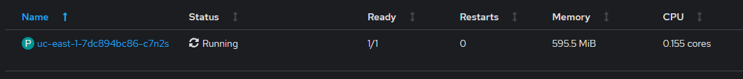
- If Tomcat crashes, a new pod will replace the failed one and the application will start in around 30 seconds. Often this is fast enough for the failed Active node to remain designated as the Active node in the cluster when the new pod has started.
- If the application becomes unresponsive, the Passive node will become Active, and the troublesome pod can be redeployed (for example, by deleting the pod).
- REST API calls and browser sessions can be load balanced between pods, transparent to the user.
If additional pods are needed for horizontal scaling, the number of Replicas can be increased in the Deployment page using the up and down arrows.
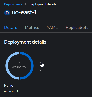
This will deploy new pods, and shortly a new Cluster Node will appear in the controller's UI, ready to accept traffic from the Service.
This process can also be automated using a Horizontal Pod Autoscaler. This will allow the Deployment to dynamically set the number of replicas based on the memory or CPU usage of the pods, either using a static value or based on the pod's resource definition.
Horizontal Pod Autoscaler
The following YAML will create an Autoscaler resource.
apiVersion: autoscaling/v2
kind: HorizontalPodAutoscaler
metadata:
name: controller-autoscaler
namespace: prod
spec:
scaleTargetRef:
apiVersion: apps/v1
kind: Deployment
name: uc-east-1
minReplicas: 2
maxReplicas: 5
metrics:
- type: Resource
resource:
name: cpu
target:
type: AverageValue
averageValue: 500m
This autoscaler targets our controller Deployment (uc-east-1).
We set the minimum and maximum number of replicas based on available resources.
The Resource section is where we define the criteria for the scaling behavior. In this example we use the CPU utilization, specifically the average utilization for all the pods in the Deployment. The value is based on CPU cores (where 500m is 5/1000s of a core).
A similar approach can be used for memory consumption. Modify the metrics field in the definition as follows:
kind: HorizontalPodAutoscaler
metrics:
- type: Resource
resource:
name: memory
target:
type: AverageValue
averageValue: 8000Mi
This will scale up the replicas when the average pod memory consumption exceeds 8GB, and scale down as the value drops below 8GB.
The other approach for determining scaling requirements is based on the Deployment's resource definition.
kind: HorizontalPodAutoscaler
metrics:
- type: Resource
resource:
name: memory
target:
type: Utilization
averageUtilization: 75
The Utilization is the ratio between the current resource usage and Request value. In this configuration it will scale the Deployment to keep the pods' memory consumption at 6GB (75% of the 8GB resource limit defined in the Deployment).
The same syntax is used for CPU utilization.
More information on resources and their use in autoscaling can be found in the OpenShift Documentation.
Health Probes (support added in 7.9.0.0)
There is an alternative for those who don't want to run multiple controllers but still want the resilience of a High Availability setup. OpenShift allows pods to be configured with various Health Probes. In UAC 7.9.0.0 a new API endpoint was added to the Controller for these probes, and requires no authentication, so they will work on an initial deployment before the admin password is set or users are created.
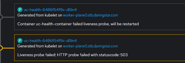
First a Startup Probe checks when the API endpoint is available and returning 200 responses, indicating that the Controller has started. This will signal to OpenShift that the pod is in Ready state. After this a Liveness Probe will run on an interval, checking this API endpoint. If the Controller enters an invalid state (for example, if it cannot read/write to the database), this API will start returning 503 responses. Based on the Liveness Probe configuration, after this API has failed the required number of times OpenShift will restart the container. This is the same scenario that would trigger an HA failover, but now we use native OpenShift functionality to failover with a single Controller instance. The following is a simplified version of the Controller Deployment with the probes added.
apiVersion: apps/v1
kind: Deployment
metadata:
  name: uc-east-1
  namespace: prod
spec:
replicas: 1
strategy:
  type: RollingUpdate
  rollingUpdate:
    maxSurge: 1
    maxUnavailable: 1
selector:
  matchLabels:
    app: uc-east-1
template:
metadata:
  labels:
    app: uc-east-1
spec:
enableServiceLinks: false
containers:
- name: uc-container
image: image-registry.openshift-image-registry.svc:5000/prod/universal-controller:7.8.0.0-ubi9
imagePullPolicy: IfNotPresent
env:
- name: UC_DB_RDBMS
value: mysql
- name: UC_DB_URL
value: jdbc:mysql://mysql.example.com:3306/
- name: UC_DB_USER
value: root
- name: UC_DB_NAME
value: UCEAST1
- name: UC_DB_PASSWORD
valueFrom:
secretKeyRef:
name: mysql-secret
key: password
startupProbe:
httpGet:
path: /uc/resources/clusternode/healthcheck
port: 8080
initialDelaySeconds: 120
timeoutSeconds: 5
failureThreshold: 10
periodSeconds: 30
livenessProbe:
httpGet:
path: /uc/resources/clusternode/healthcheck
port: 8080
initialDelaySeconds: 5
timeoutSeconds: 5
failureThreshold: 3
The Startup Probe waits 120 seconds after startup before beginning (initialDelaySeconds). This should give the Controller time to startup and connect to the database. Then it will run an HTTP GET request on the /uc/resources/clusternode/healthcheck endpoint every 30 seconds (periodSeconds). If the request times out after 5 seconds (timeoutSeconds) or returns a non-200 response code it will fail. After 10 failures (failureThreshold) it will restart the container. Otherwise it will mark the pod as Ready. (These options might need to be adjusted if the probe fails before the database is bootstrapped on a fresh deployment.)
The Liveness Probe has the same options, but it will not begin executing until after the Startup Probe succeeds. This probe's configuration will affect the failover. In this case we consider the Controller to be unhealthy after 3 failed attempts with a 5 second timeout and the default period (10 seconds).
When a probe fails it will generate an Event, which can be viewed in the OpenShift Dashboard. After the failure condition is met another Event shows that the container is restarted.
Controller Service
With the pods deployed, we need to create a service to allow clients to communicate with the Controller. We will create a service with the following YAML.
apiVersion: v1
kind: Service
metadata:
  name: uc-east-1-service
  namespace: prod
spec:
  selector:
    app: uc-east-1
  ports:
    - name: http
      protocol: TCP
      port: 8080
    - name: https
      protocol: TCP
      port: 8443
The selector determines which pods to connect to based on a label. In this case we use the label app with the value uc-east-1 to connect to our Controller pods.
Here we use the default type (ClusterIP) which provides an internal IP address for load balancing to endpoints. These endpoints are determined by the selector. Any traffic routed to the service will be load balanced between our two (or more) controller pods.
The port defines which port on the pod the service should connect to. Here we have both HTTP and HTTPS ports defined for use with different route configurations (see Controller TLS Configuration), but likely only one will be needed.
Controller Route
To connect to the service from outside the cluster we must expose it with a Route using the following YAML.
apiVersion: route.openshift.io/v1
kind: Route
metadata:
  name: controller
  namespace: prod
spec:
  to:
    kind: Service
    name: uc-east-1-service
  port:
    targetPort: https
  tls:
    termination: reencrypt
    insecureEdgeTerminationPolicy: None
    certificate: |-
      -----BEGIN CERTIFICATE-----
      MIIGATCCA+mgAwIBAgIUYNs+Ai82V9hBYfAZzNICwNCdPNQwDQYJKoZIhvcNAQEL
      n7f0n38=
      -----END CERTIFICATE-----
    key: |-
      -----BEGIN PRIVATE KEY-----
      MIIJQgIBADANBgkqhkiG9w0BAQEFAASCCSwwggkoAgEAAoICAQC9sUl1XfQoHz9+
      AFhYBLQV3D5wsZ1BV5PQlaOj6aT7+g==
      -----END PRIVATE KEY-----
    caCertificate: |-
      -----BEGIN CERTIFICATE-----
      MIIFuTCCA6GgAwIBAgIUSvuxR4t/z4JrAN8vzMU4NtPG80gwDQYJKoZIhvcNAQEL
      lLdrmtapXbcdAFcQQBQG5BARvkQEuGPHznmqdLI=
      -----END CERTIFICATE-----
    destinationCACertificate: |-
      -----BEGIN CERTIFICATE-----
      MIIFuTCCA6GgAwIBAgIUSAASCCSwwggkoAgEAAoICAQC9sUlPG80gwDQYJKoZI1L
      A+mgAwIBAgIUYNs+Ai82V9hBYfA=
      -----END CERTIFICATE-----
This creates a URL with the format https://ROUTE-PROJECT.SUBDOMAIN such as https://controller-route-prod.example.com.
This configuration uses Re-encrypt TLS Termination. This is the most secure approach, and follows the Zero Trust Networking policy. The certificate, key, and caCertificate fields define the certificates for connections to the Route. The destinationCACertificate field defines the CA for Tomcat, corresponding to the certificate and private key added in the Secret. For more information on route types see Controller TLS Configuration.
In the Re-encrypt TLS configuration we must specify that we want to connect to the HTTPS port of the controller pods, since we want the internal cluster traffic to be encrypted.
HTTP traffic will not be allowed, as specified by the field insecureEdgeTerminationPolicy. HTTP traffic can be allowed (allow) or redirected to HTTPS (redirect) depending on the use case.
Controller TLS Configuration
There are two configuration options for the TLS Termination on the route:
- Re-encrypt (Recommended)
- Edge
Re-encrypt
Using Re-encrypt TLS Termination traffic between the client and cluster's router will be encrypted using the specified certificates, as with Edge. Additionally, traffic between the router and the pod is encrypted with a different set of certificates, providing end-to-end encryption for all traffic. This means the route must connect to the HTTPS port on the pod.
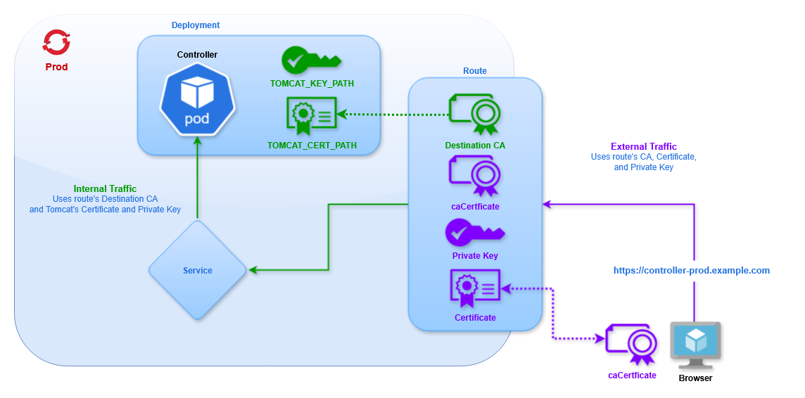
The certificates for external traffic are defined the same as Edge (they may also be omitted to use the cluster's defaults). Then we must specify the CA Certificate for internal traffic, corresponding to the certificates defined for Tomcat in the Secret.
apiVersion: route.openshift.io/v1
kind: Route
metadata:
  name: controller
  namespace: prod
spec:
  to:
    kind: Service
    name: uc-east-1-service
  port:
    targetPort: https
  tls:
    termination: reencrypt
    insecureEdgeTerminationPolicy: None
    destinationCACertificate: |-
      -----BEGIN CERTIFICATE-----
      MIIFuTCCA6GgAwIBAgIUSAASCCSwwggkoAgEAAoICAQC9sUlPG80gwDQYJKoZI1L
      A+mgAwIBAgIUYNs+Ai82V9hBYfA=
      -----END CERTIFICATE-----
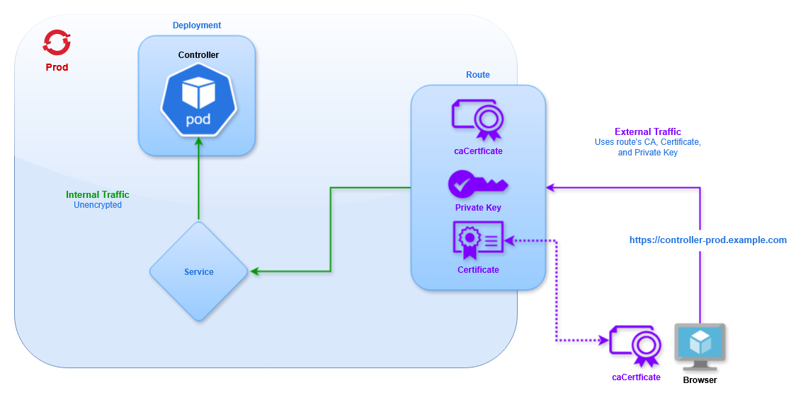
Edge
Using Edge TLS Termination traffic between the client and cluster will be encrypted using the specified certificates. Traffic between the cluster's router and the pod will not be encrypted. This type of Route must use the HTTP target port, even though the route's URL will use HTTPS.
Here is an example Route definition using Edge TLS termination:
apiVersion: route.openshift.io/v1
kind: Route
metadata:
  name: controller
  namespace: prod
spec:
  to:
    kind: Service
    name: uc-east-1-service
  port:
    targetPort: http
  tls:
    termination: edge
    insecureEdgeTerminationPolicy: None
    certificate: |-
      -----BEGIN CERTIFICATE-----
      MIIGATCCA+mgAwIBAgIUYNs+Ai82V9hBYfAZzNICwNCdPNQwDQYJKoZIhvcNAQEL
      n7f0n38=
      -----END CERTIFICATE-----
    key: |-
      -----BEGIN PRIVATE KEY-----
      MIIJQgIBADANBgkqhkiG9w0BAQEFAASCCSwwggkoAgEAAoICAQC9sUl1XfQoHz9+
      AFhYBLQV3D5wsZ1BV5PQlaOj6aT7+g==
      -----END PRIVATE KEY-----
    caCertificate: |-
      -----BEGIN CERTIFICATE-----
      MIIFuTCCA6GgAwIBAgIUSvuxR4t/z4JrAN8vzMU4NtPG80gwDQYJKoZIhvcNAQEL
      lLdrmtapXbcdAFcQQBQG5BARvkQEuGPHznmqdLI=
      -----END CERTIFICATE-----
The fields for certificate, key, and caCertificate are the same as the Re-encrypt route, and handle encryption for traffic between clients and the Cluster Router.
These fields can be omitted, and the certificates of the Router will be used.
apiVersion: route.openshift.io/v1
kind: Route
metadata:
  name: controller
  namespace: prod
spec:
  to:
    kind: Service
    name: uc-east-1-service
  port:
    targetPort: http
  tls:
    termination: edge
    insecureEdgeTerminationPolicy: None
Verification
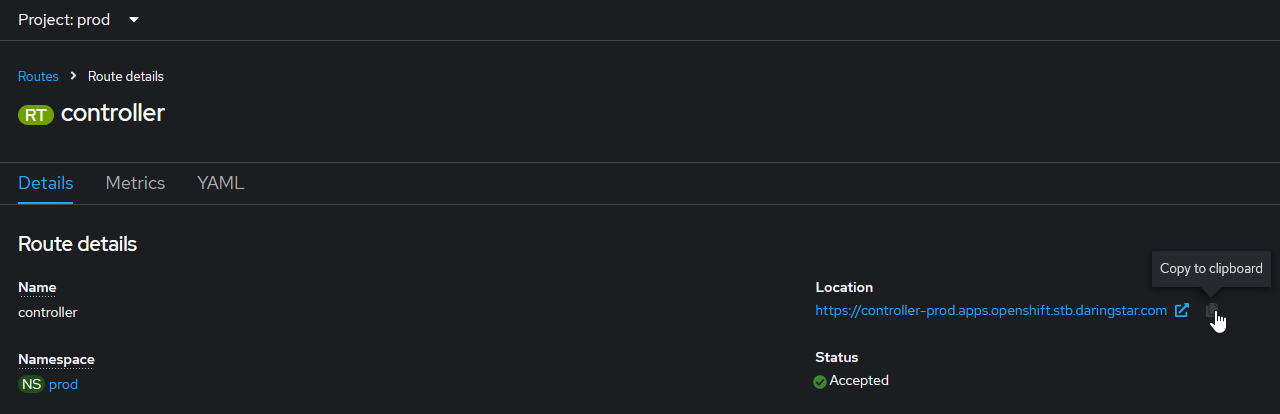
Once all of the resources are created we can access the UI using the route (the URL will be provided in the route page). Make sure to append /uc to the end of the URL to access the Controller login page.
Set the admin password and login. We should see two Cluster Nodes (not to be confused with the OpenShift cluster's nodes).
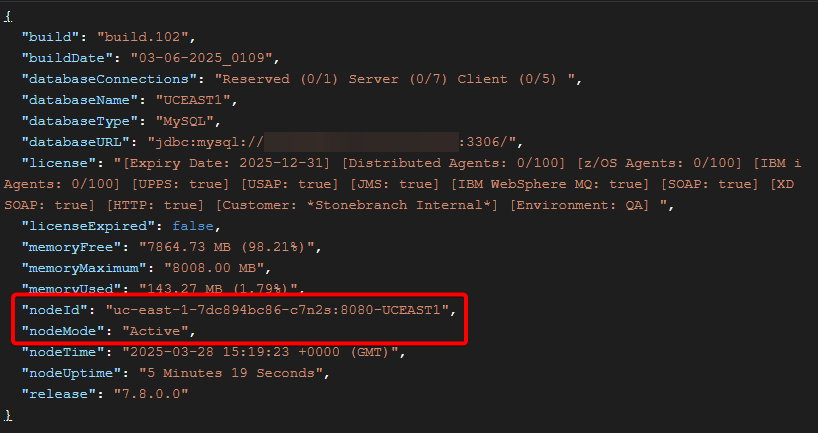
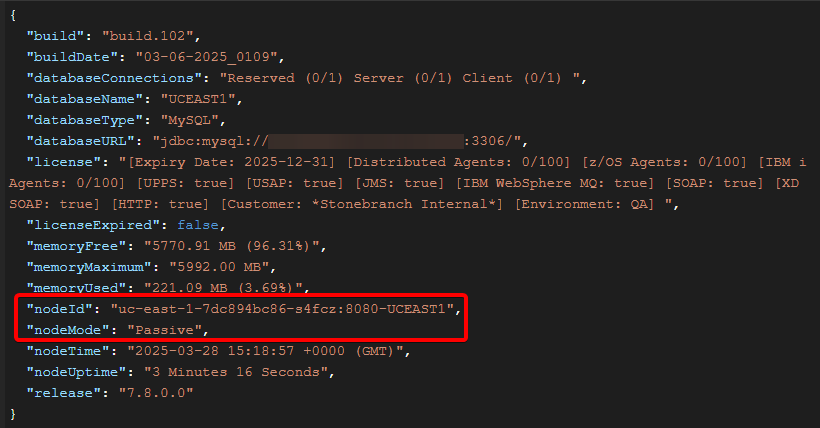
We can verify the Service is correctly load balancing by using the Retrieve System Details API, which shows the name of the controller pod where the request ran.
For example, two consecutive requests are routed to different pods:
Universal Agent Setup
We will deploy 4 Universal Agents: 1 OMS pod, 2 UAG pods, and 1 external agent that connects into the cluster. The OpenShift agents will also use Deployments to allow rolling out new pods with the latest configuration.
OMS Server
OMS Deployment
The following YAML creates a Deployment containing 1 Universal Agent for OMS.
- Deployment
- Description
apiVersion: apps/v1
kind: Deployment
metadata:
  name: oms-east-1
  namespace: prod
spec:
  replicas: 1
  strategy:
    type: RollingUpdate
    rollingUpdate:
      maxSurge: 1
      maxUnavailable: 0
  selector:
    matchLabels:
      app: oms-east-1
  template:
    metadata:
      labels:
        app: oms-east-1
    spec:
      enableServiceLinks: false
      containers:
        - name: oms-container
          image: image-registry.openshift-image-registry.svc:5000/prod/universal-agent:7.8.0.0-ubi9
          imagePullPolicy: IfNotPresent
          env:
            - name: OMS_PORT
              value: "7878"
            - name: OMSAUTOSTART
              value: "YES"
            - name: UAGAUTOSTART
              value: "NO"
Configuration | Description |
|---|---|
| The name of the Deployment is |
| We will only use 1 pod, which is determined by the |
| To ensure we always have a pod available we will use the |
| The selector tells the Deployment which Pods to manage based on a label, which is why the |
| We apply the label |
| We want to disable the Service environment variables, so we set |
| We define a single container, which uses the image |
| The Universal Agent configuration is handled by Environment Variables. We will start OMS and not start UAG, and define the OMS port for use with the service. Additional configuration options can be found for UAG and OMS. info The values for the Environment Variables must be strings, which is why the integer and boolean values must be quoted. |
OMS Service
With the pod deployed we need to create a service to allow clients to communicate with the OMS. We will create a service with the following YAML.
apiVersion: v1
kind: Service
metadata:
name: oms-east-1-service
namespace: prod
spec:
selector:
app: oms-east-1
ports:
- name: oms
protocol: TCP
port: 7878
The selector determines which pods to connect to based on a label. In this case we use the label app with the value oms-east-1 to connect to our OMS pod.
The port defines which port on the pod the service should connect to, in this case the default OMS port.
Other pods in the cluster can interact with the service by name. For example, you can add this OMS in the Universal Controller using any of the following hostnames:
-
oms-east-1-service
-
oms-east-1-service.prod.svc
-
oms-east-1-service.prod.svc.cluster.local
OMS Route
To connect to the service from outside the cluster we must expose it with a Route using the following YAML.
apiVersion: route.openshift.io/v1
kind: Route
metadata:
name: oms-east-1-route
namespace: prod
spec:
to:
kind: Service
name: oms-east-1-service
tls:
termination: passthrough
insecureEdgeTerminationPolicy: None
This creates a URL with the format https://ROUTE-PROJECT.SUBDOMAIN such as https://oms-east-1-route-prod.example.com.
To create a custom hostname that isn't based on the route name the host attribute can be defined, such as:
apiVersion: route.openshift.io/v1
kind: Route
metadata:
name: oms-east-1-route
namespace: prod
spec:
host: oms1.apps.example.com
to:
kind: Service
name: oms-east-1-service
tls:
termination: passthrough
insecureEdgeTerminationPolicy: None
DNS should direct traffic at from *.apps.example.com to the cluster's nodes. From there the cluster Router directs traffic to the correct service based on the route's hostname (eg, oms1 will go to the oms-east-1-service selected in the route) using TLS SNI headers.
This configuration uses TLS Passthrough. This sends encrypted traffic directly to the OMS, without any TLS Termination from the Router. All of the certificates and keys are handled directly by OMS and clients, so none are provided on the Route definition.
TLS SNI
In order for traffic to be routed to the correct service the client must use TLS SNI headers. This will tell the load balancer (HAProxy in this case) which route the client is trying to access. For Universal Agents this requires setting the oms_servers value for UAG using the format PORT@HOSTNAME:SNI-HOSTNAME which for OpenShift will be PORT@ROUTE:ROUTE. In the above example that would be 443@oms1.apps.example.com:oms1.apps.example.com. The port is 443 because the route is exposed on the default HTTPS port. The SNI Hostname is the same as the route name, so it is specified twice. With this configuration UAG will be able to connect into the cluster, through the route, to the service, and into the pod on the OMS port.
UAG Agents
Deployment
The following YAML creates a Deployment containing 1 Universal Agent running UAG.
apiVersion: apps/v1
kind: Deployment
metadata:
name: uag-east-1
namespace: prod
spec:
replicas: 1
strategy:
  type: RollingUpdate
  rollingUpdate:
    maxSurge: 1
    maxUnavailable: 0
selector:
matchLabels:
app: uag-east-1
template:
metadata:
labels:
app: uag-east-1
spec:
hostname: uag-east-1
enableServiceLinks: false
containers:
- name: uag-container
image: image-registry.openshift-image-registry.svc:5000/prod/universal-agent:7.8.0.0-ubi9
imagePullPolicy: IfNotPresent
env:
- name: UAGOMSSERVERS
value: oms-east-1-service
- name: OMSAUTOSTART
value: "NO"
- name: UAGAUTOSTART
value: "YES"
- name: UAGNETNAME
value: AGENT1
The majority of this is the same as the OMS Deployment.
The Agent will connect to the OMS we just deployed by connecting to its service (specified in the UAGOMSSERVERS configuration). Since it is inside the cluster it does not need to connect to the route using TLS SNI.
We will set OMS to not start, UAG to start, and set a desired netname.
Note the hostname field (spec.template.spec.hostname). When not specified the container's hostname will be set to the Pod name. In a Deployment the Pod's name will include a randomly generated string. This will affect the name of the Agent as it appears in the Controller. Depending on the use case this might not be desired. Statically defining the hostname will ensure that when the Pod is recreated (for example, after making a configuration change, or when the Pod is restarted) the same Agent record will be used in the Controller. If the hostname is not specified a new Agent record will appear with the new Pod name included in the agent's name.
Another alternative is to use Transient Agents. By setting the environment variable UAGTRANSIENT: 'YES' the Agent record will be deleted from the Controller when the Agent stops. So when a Pod is restarted the old Agent (with the old Pod name) will be removed from the Controller, and a new Agent (with the new Pod name) will be created. It should be understood that Transient Agents should never be specified directly in any task definition. They are designed to accept work via an Agent Cluster, so when configuring an agent to be transient we must ensure that the agent registers with one or more Agent Clusters. This can be configured using the UAGAGENTCLUSTERS environment variable.
Next create a Deployment for the second UAG pod.
apiVersion: apps/v1
kind: Deployment
metadata:
name: uag-east-2
namespace: prod
spec:
replicas: 1
strategy:
type: RollingUpdate
rollingUpdate:
maxSurge: 1
maxUnavailable: 0
selector:
matchLabels:
app: uag-east-2
template:
metadata:
labels:
app: uag-east-2
spec:
hostname: uag-east-2
enableServiceLinks: false
containers:
- name: uag-container
image: image-registry.openshift-image-registry.svc:5000/prod/universal-agent:7.8.0.0-ubi9
imagePullPolicy: IfNotPresent
env:
- name: UAGOMSSERVERS
value: oms-east-1-service
- name: OMSAUTOSTART
value: "NO"
- name: UAGAUTOSTART
value: "YES"
- name: UAGNETNAME
value: AGENT2
- name: UBRMAXSSLPROTOCOL
value: TLS1_3
- name: UCMDMAXSSLPROTOCOL
value: TLS1_3
- name: UDMMAXSSLPROTOCOL
value: TLS1_3
To create a second Agent we only need to modify a few fields:
- Deployment name
- Selector labels
- Deployment labels
- Container hostname
- Agent netname
To demonstrate other configuration options this Agent will use TLS1.3 for all connections between UCMD/UDM and UBroker.
Both Agents (and the external agent added in the next section) will connect to the OMS pod. As the number of Agents increases it is important to scale the number of OMS Servers accordingly. This will be case-specific, so we can't recommend any particular scale factor, but it is important to keep in mind.
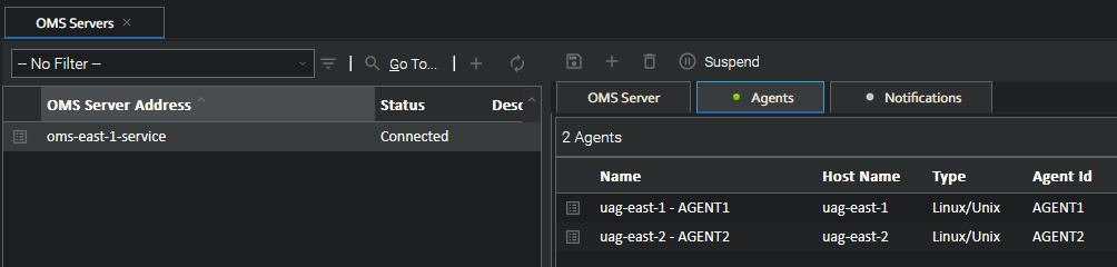
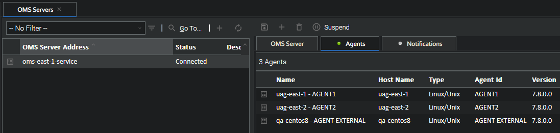
With the OMS already added in the Controller when the UAG pods start we will see them appear under the OMS Server's agents.
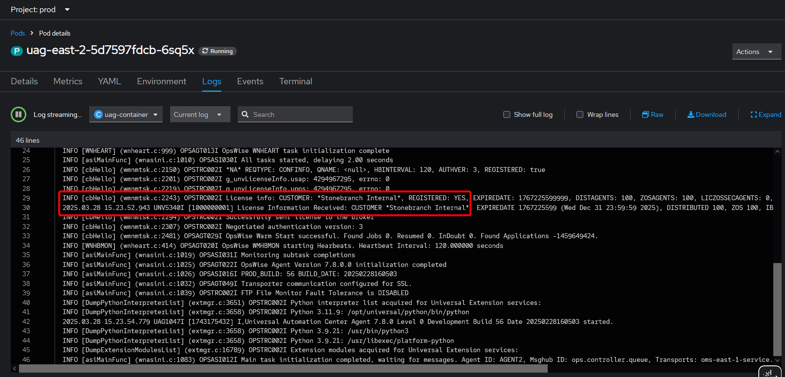
The pod log shows that UAG successfully got a license from the controller.
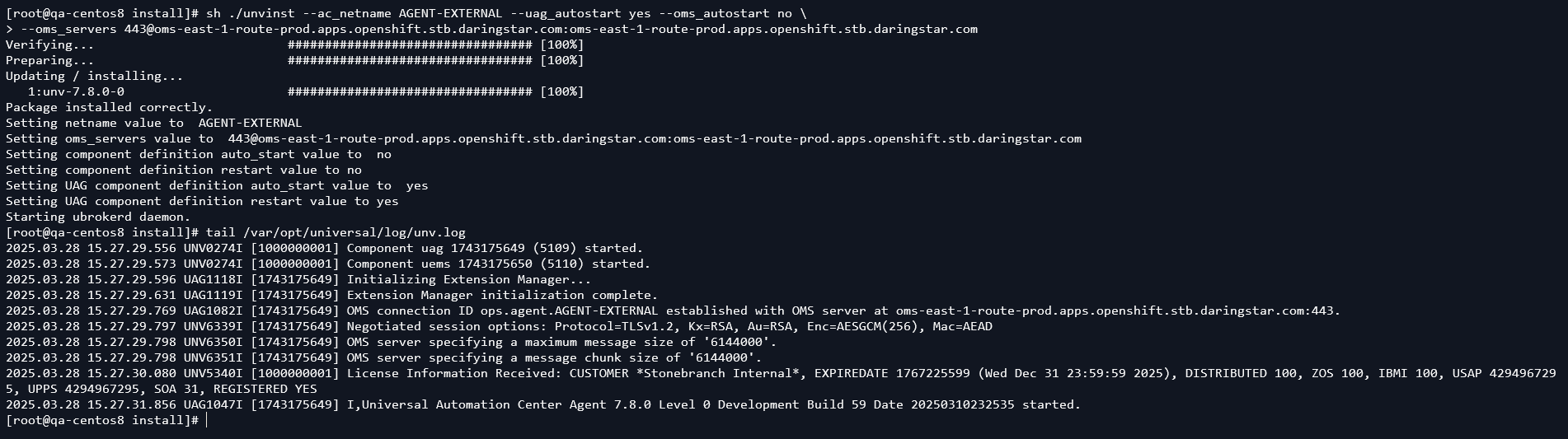
UAG Agent (External)
We will also create another Agent running outside the cluster (it could be on-premises or in the cloud) that will connect to the OpenShift OMS and Universal Controller. This will demonstrate the TLS SNI functionality.
This Agent can run on any platform, as long as it has network access to the OpenShift cluster and is at least version 7.8.0.0 (to support TLS SNI).
The Agent should be installed in the normal way (described in the Universal Agent documentation). We only need to configure the UAG option for oms_servers. Depending on the platform this can be done during installation, otherwise the configuration file will need to be updated.
Platform | Configuration |
|---|---|
Linux/Unix | During installation use the |
Windows (system mode) | During installation use the |
Windows (user mode) | During installation use the |
IBM i | After installation modify the UAG configuration in |
z/OS | After installation modify the UAG configuration in |
The value should be 443@oms1.apps.example.com:oms1.apps.example.com (assuming the route with custom hostname was used). This specifies the TLS SNI hostname that allows UAG to connect to the OMS inside the cluster.
In this example we do a clean install on a CentOS 8 host. We can see UAG connects to the OMS and gets a license from the controller.
Then the Agent appears in the Controller under the OMS Server, alongside the OpenShift agents.
UDM (support added in 7.9.0.0)
UDM requires connecting to a remote agent's UBroker port for transferring files between agents. If one of these agents is in an OpenShift cluster this connection needs to go through the Router to connect to the pod, which requires the same TLS SNI headers added for OMS. This section describes how to configure a "UAG" pod to accept UDM connections from external agents.
UAG Service
First, we need to create a service and route for connecting to the agent's broker port.
apiVersion: v1
kind: Service
metadata:
name: uag-east-1-service
namespace: prod
spec:
selector:
app: uag-east-1
ports:
- name: ubroker
protocol: TCP
port: 7887
The selector determines which pods to connect to based on a label. In this case, we use the label app with the value uag-east-1 to connect to our first UAG pod.
The port defines which port on the pod the service should connect to, in this case the default UBroker port.
UAG Route
Next, we need to create a route to access this service from outside the cluster.
apiVersion: route.openshift.io/v1
kind: Route
metadata:
name: uag-east-1-route
namespace: prod
spec:
to:
kind: Service
name: uag-east-1-service
tls:
termination: passthrough
insecureEdgeTerminationPolicy: None
This creates a URL with the format https://ROUTE-PROJECT.SUBDOMAIN such as https://uag-east-1-route-prod.example.com.
This configuration uses TLS Passthrough. This sends encrypted traffic directly to UBroker, without any TLS Termination from the Router. All of the certificates and keys are handled directly by UBroker and clients, so none are provided on the Route definition.
Verification
With the service and route created we can now run UDM scripts from any agent (internal or external to the cluster) connecting to our UAG pod. The only change needed to connect to an OpenShift agent compared with a normal agent is in the open command. Here is an example of normal script syntax to copy a single file from a remote agent to a local one:
open dst=local src=agent1.example.com port=7887 xfile=credentials.txt
copy src=/tmp/data.txt dst=/home/ubroker/data.txt
close
To run this same script for an Openshift agent we only need to change the open command:
open dst=local src=uag-east-1-route-prod.example.com port=443 sni=uag-east-1-route-prod.example.com
copy src=/tmp/data.txt dst=/home/ubroker/data.txt
close
Here we use the Route name for the target (src) and sni attribute (and the port must be 443 to hit the https endpoint of the Router). As with OMS, this sets the TLS SNI headers which tells the Openshift Router which route it's using, and therefore which service to connect to.
File Transfer Tasks
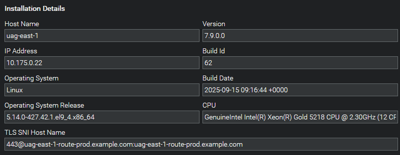
This same functionality can be achieved for File Transfer tasks in the controller. When using UDM in a File Transfer task the task will generate a UDM script and the agent will execute it. Normally the script will use the IP address reported from the agent for the open command. This will not work on OpenShift, as the pod IP is a cluster-specific IP range that external agents cannot access. The script will also not include any SNI information. To get the correct connection information for OpenShift agents we will use the UAG config option tls_sni_hostname (or environment variable UAGTLSSNIHOSTNAME). This tells the controller the hostname, port, and SNI hostname to use in UDM scripts.
Update the 1st UAG Deployment to use the UAGTLSSNIHOSTNAME variable with the values from the newly created route:
apiVersion: apps/v1
kind: Deployment
metadata:
  name: uag-east-1
  namespace: prod
spec:
  replicas: 1
  strategy:
    type: RollingUpdate
    rollingUpdate:
      maxSurge: 1
      maxUnavailable: 0
  selector:
    matchLabels:
      app: uag-east-1
  template:
    metadata:
      labels:
        app: uag-east-1
    spec:
      hostname: uag-east-1
      enableServiceLinks: false
      containers:
        - name: uag-container
          image: image-registry.openshift-image-registry.svc:5000/prod/universal-agent:7.8.0.0-ubi9
          imagePullPolicy: IfNotPresent
          env:
            - name: UAGOMSSERVERS
              value: oms-east-1-service
            - name: OMSAUTOSTART
              value: "NO"
            - name: UAGAUTOSTART
              value: "YES"
            - name: UAGNETNAME
              value: AGENT1
- name: UAGTLSSNIHOSTNAME
value: 443@uag-east-1-route-prod.example.com:uag-east-1-route-prod.example.com
This information will then appear in the controller's Agents page:
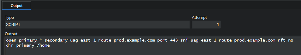
Running a File Transfer task using this agent will reveal how the correct script content is generated:
The tls_sni_hostname option should not be specified for external agents. This option is specifically for containerized agents for use with File Transfer tasks. Using the option for external agents can cause incorrect File Transfer behavior.
USAP
In order to use the Universal Connector for SAP the Agent must have access to the SAP NW (NetWeaver) RFC libraries. These are not provided in the Universal Agent image and must be obtained from SAP. More information can be found in the Universal Agent documentation.
Once the libraries are downloaded they must be added to the container. There are two methods to accomplish this: create a new agent image with the libraries included, or mount a volume where the libraries are stored.
- New Image
- Persistent Volume
Create a new Image
One option is to build a new SAP-enabled image using the Universal Agent image as the source. With Docker installed follow these steps to create the image.
Step | Description |
|---|---|
Copy | Copy the SAP-RFC libraries into a local directory: |
Create | Create a simple dockerfile |
Build | Build the new image using Docker This will create a new local image with the tag |
Tag and Push | Add a remote tag and push the image to the cluster as described in Pushing Images to the Cluster |
Add a Persistent Volume
The other option is to mount the libraries into the agent containers using a Persistent Volume.
Step | Description |
|---|---|
Create Claim | Create a Persistent Volume Claim, which will obtain a Persistent Volume when the pod is started. info The storage class will vary depending on how storage is setup on cluster, which will depend on the platform (local, Azure, AWS, etc). This will also impact the access mode, as different modes may be unavailable depending on the storage configuration. |
Update Agent Deployment | Modify the UAG Agent Deployment YAML with the following changes
|
Copy Libraries to Volume | Once the Deployment starts the pod the Persistent Volume will be claimed and mounted. Then we need to copy the libraries into the volume with This is a one-time operation. Other Pods that use this volume can access the same libraries. As long as the volume is mounted in a Pod the data in the volume will remain. If no Pods are connected, and the volume becomes unclaimed, the behavior varies depending on the cluster's storage configuration. |
Pros and Cons
There are pros and cons for each method. We describe a few here, but ultimately the best method depends on the individual use case.
Scenario | New Image | Persistent Volume |
|---|---|---|
Red Hat Image Catalog | The image from the Red Hat catalog will need to be downloaded locally and modified. | Using the image from the Red Hat catalog requires no modification. |
Updating Images | Changing source images requires building a new SAP image. | Updating to a new version (or a new image) requires no further changes. |
Dependencies | No additional OpenShift resources are required. | The Persistent Volume may impact which Node a Pod can run on, impacting load distribution. |